Wiring Diagram 2017 Ford Transit Van
This is a quick no-frills Remote Start Pictorial on the 2015 - 2018 Ford Transit. These are the full size replacements for the Econoline series of vans, not the smaller Transit Connect series. This install will cover the common work vans, not the passenger vans with many rows of seats. This van was a 2017 Transit 250. It had the 3.7 L engine, no Factory Alarm system and no PATS engine immobilizer system. Most work vans do not come with the PATS system. The van did have power locks and "one-touch" starting. The factory key FOB's include the power lock control buttons and continue to function during a remote start-up so a simple One Button Remote Start system was chosen to provide a bit of extra range over the factory remotes and a 3x Lock system.
There are many brands and models or R/S system to choose from. The Avital 4113 / 4115 and the Viper equivalents, Compustar CS801-s and CS910-s and the Prestige APS901E or the newer APS901Z are all excellent low cost 1-way units. For this install I used an Avital 4115. No PATS system means no bypass module, less money and a very simple install.
While this Pictorial includes photos of the lower dash removal, I would recommend that before attempting this install you visit YouTube and do a search on "2015+ transit remote start". There is a 14 minute video posted that shows all the necessary trim panel removal in good detail.
Disassembly :
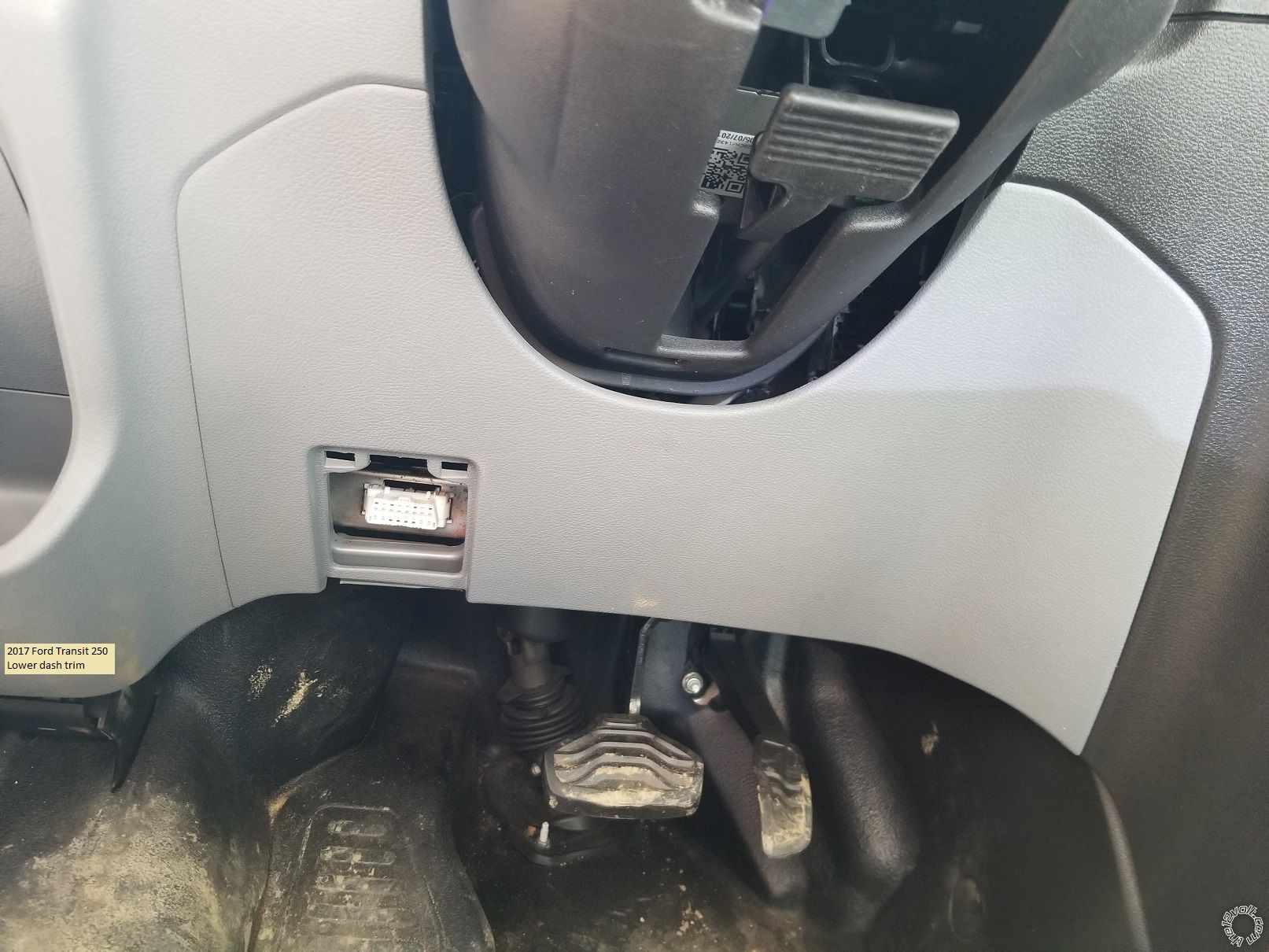
First pull the trim panel below the steering wheel off.
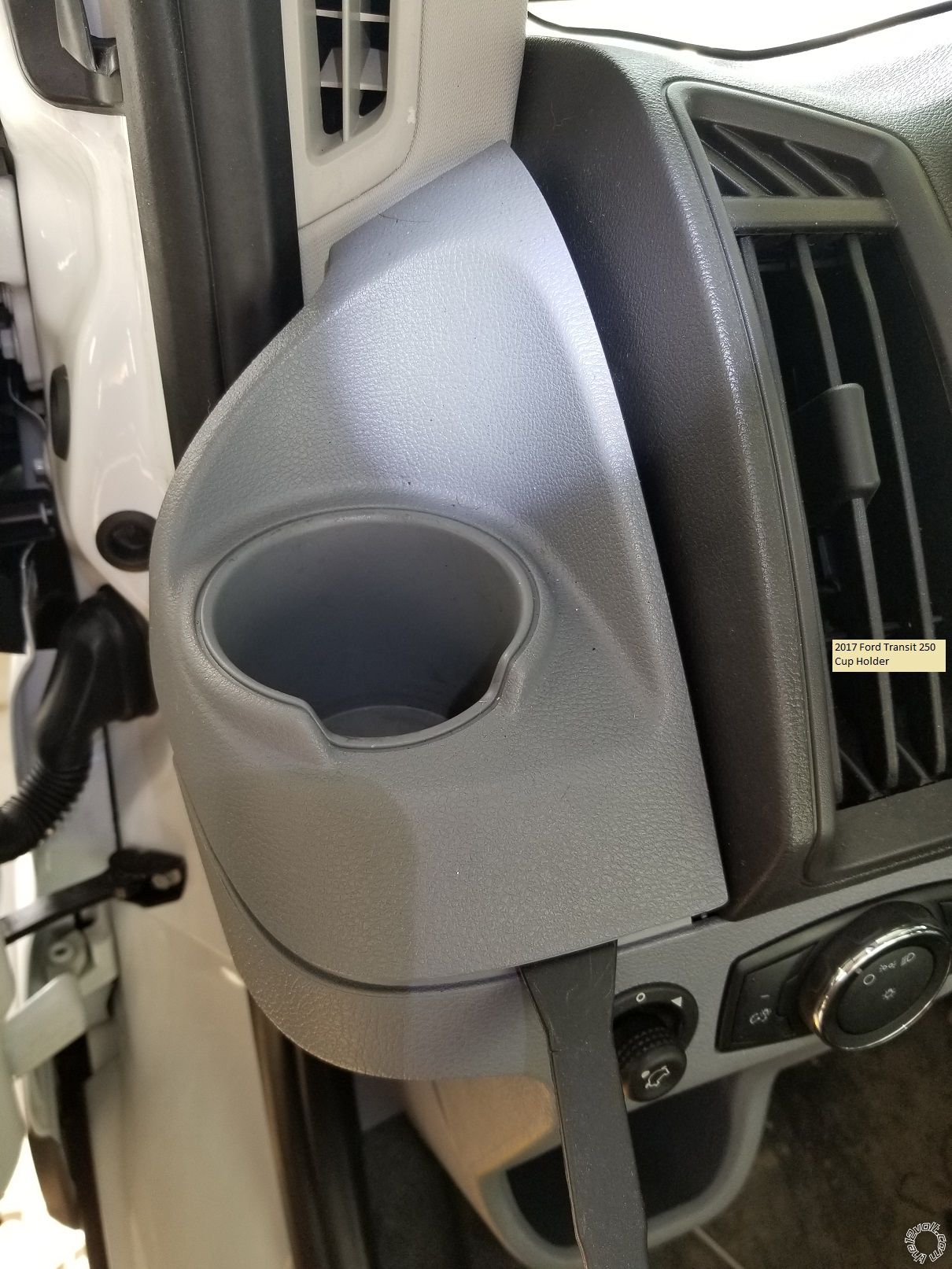
Next use a trim tool to pop the cup holder up and off.
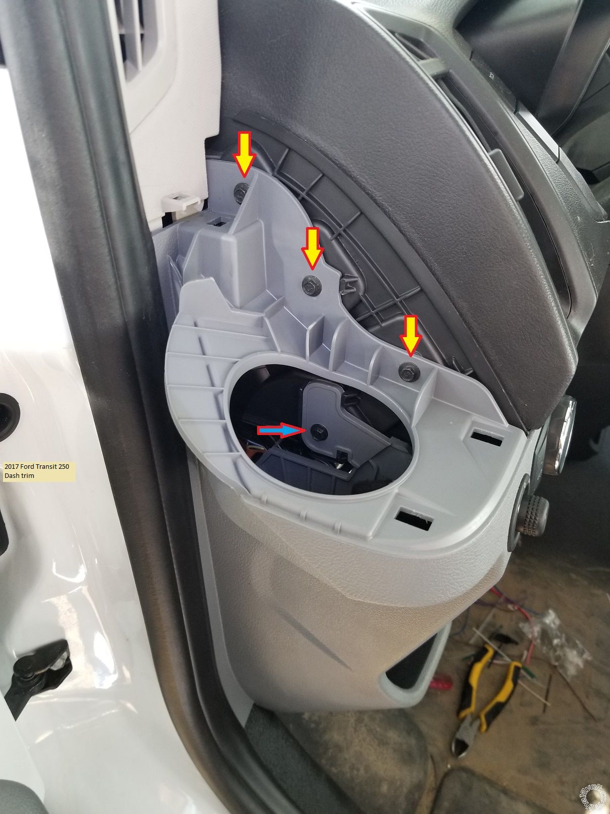
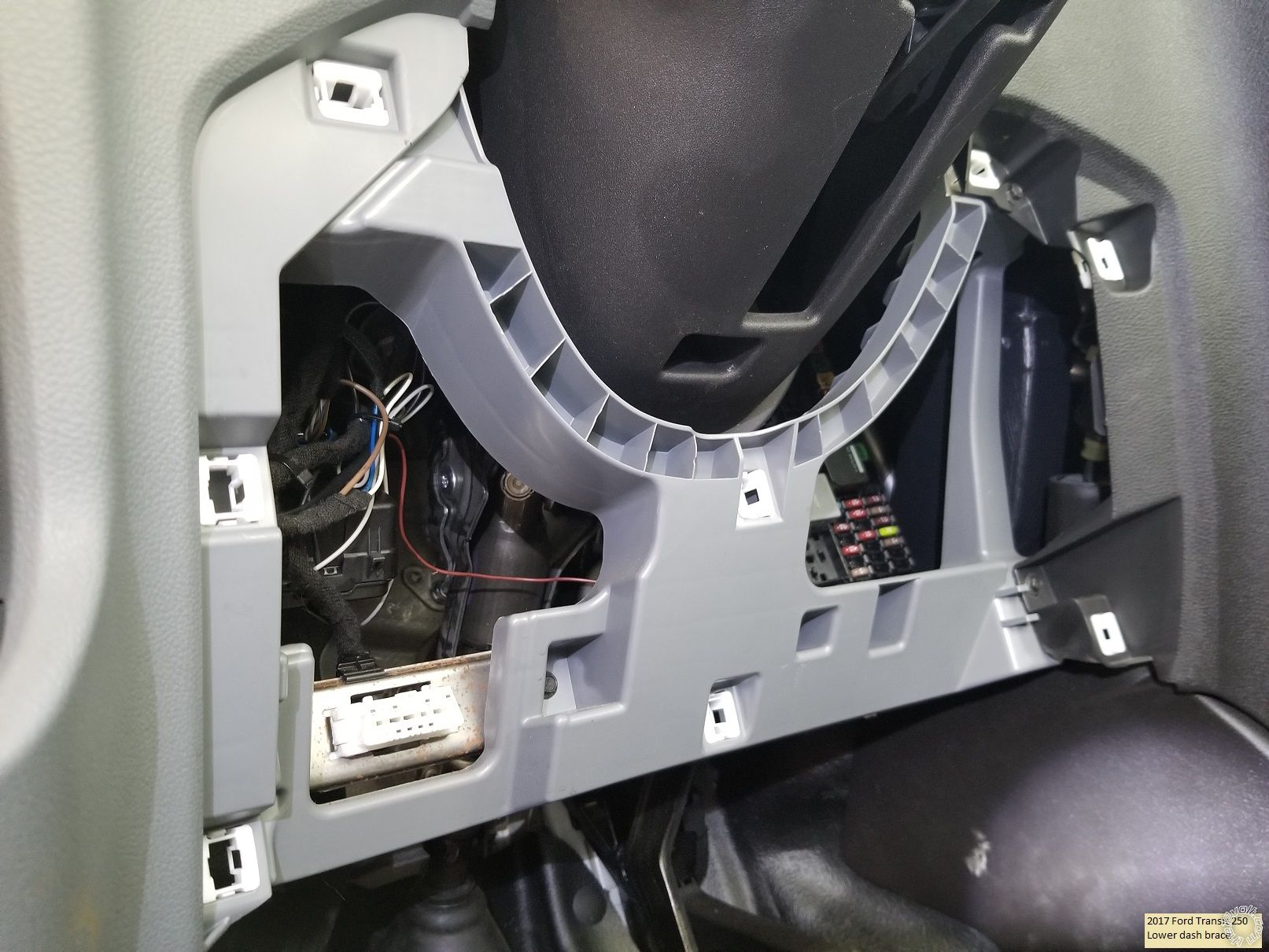
Use a 7mm socket to remove the three screws shown.
Remove the fuse access panel and then the two 7mm screws indicated.
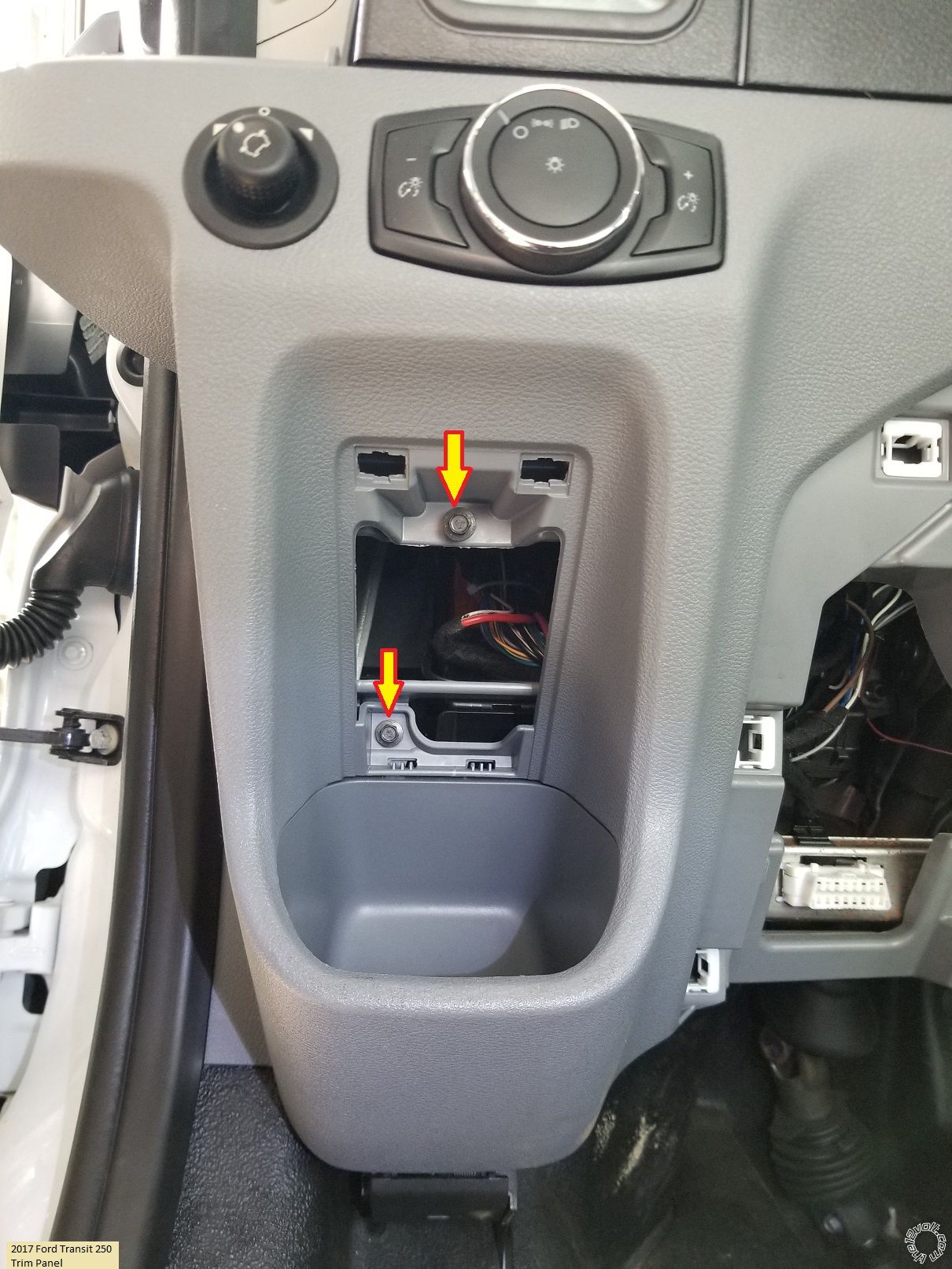
Release and pull this left side trim piece away from the dash.
To remove the inner brace panel, remove the seven 7mm screws. This is shown in good detail in the previously mentioned video. One screw is on the left side. You must gently lift the center console trim to access one hidden screw at the top right corner on the brace panel.
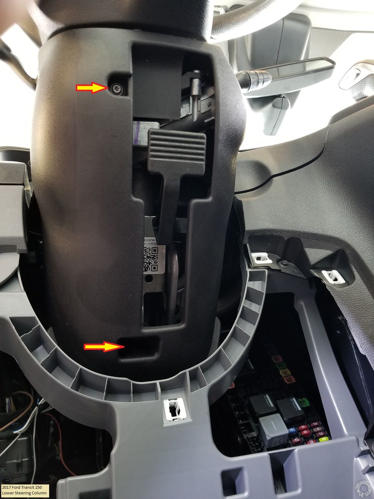
Remove the two T20 Torx screws indicated at the bottom of the steering column. Then turn the steering wheel to expose plastic releases at the 10 and 2 o'clock positions. Separate the steering column cover halves and remove the bottom piece.
That's it for trim removal. At this point you should verify that there is no black plastic PATS antenna and connector on the ignition switch. Below is a photo of this Transit without the PATS system. If you have the PATS antenna, you will need a bypass module.
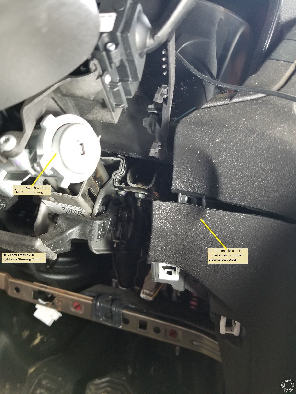
Wiring :
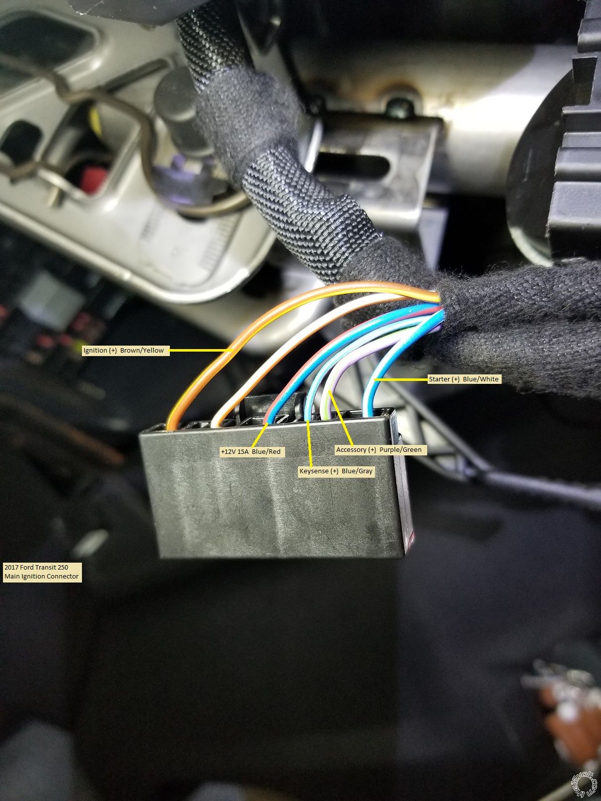
Here is a photo of the main Ignition connector removed from the plug with the wires marked. Only 3 connections are needed, IGN, ACC and Starter.
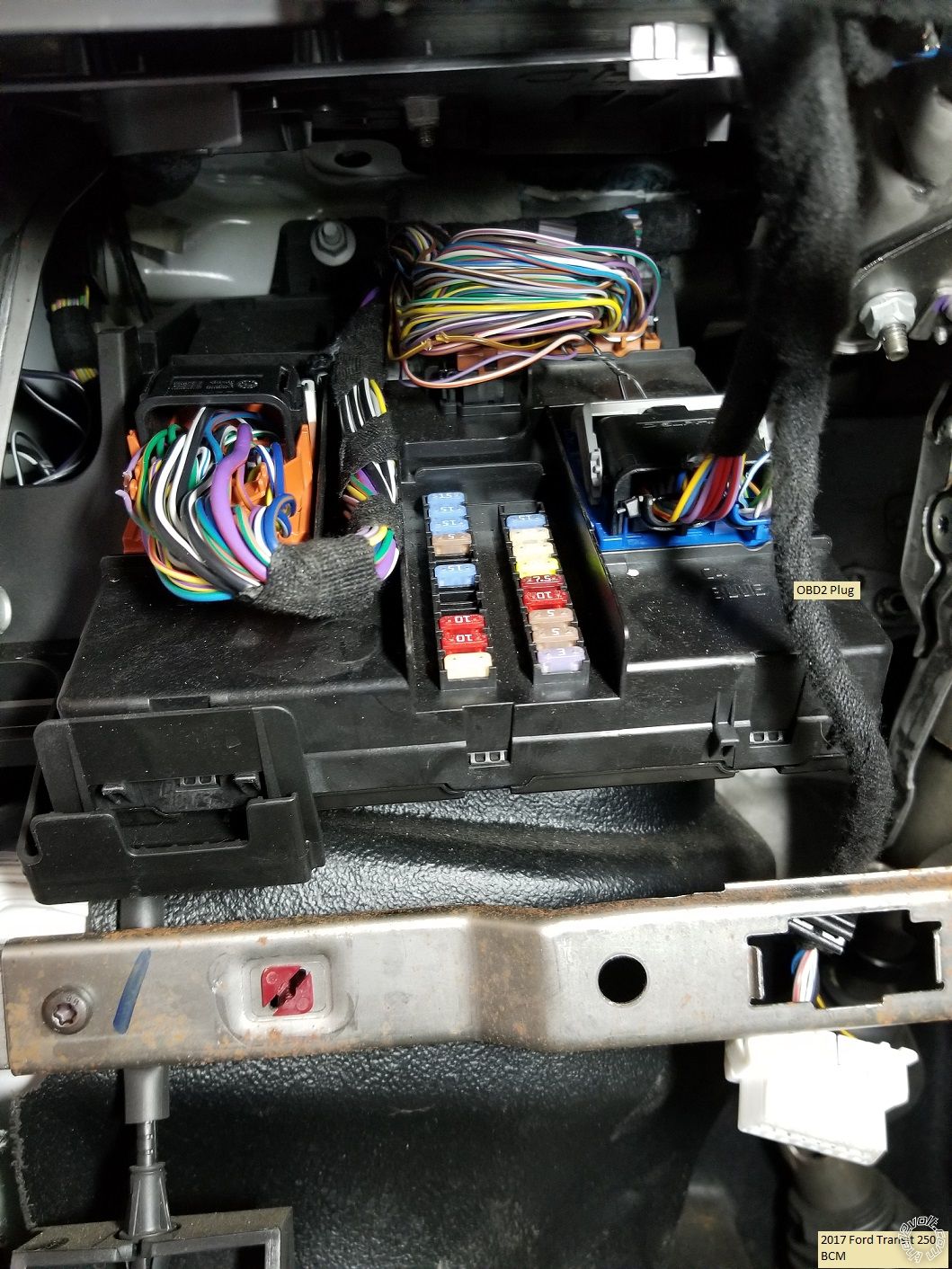
Below is a photo of the vans BCM located to the left of the steering column.
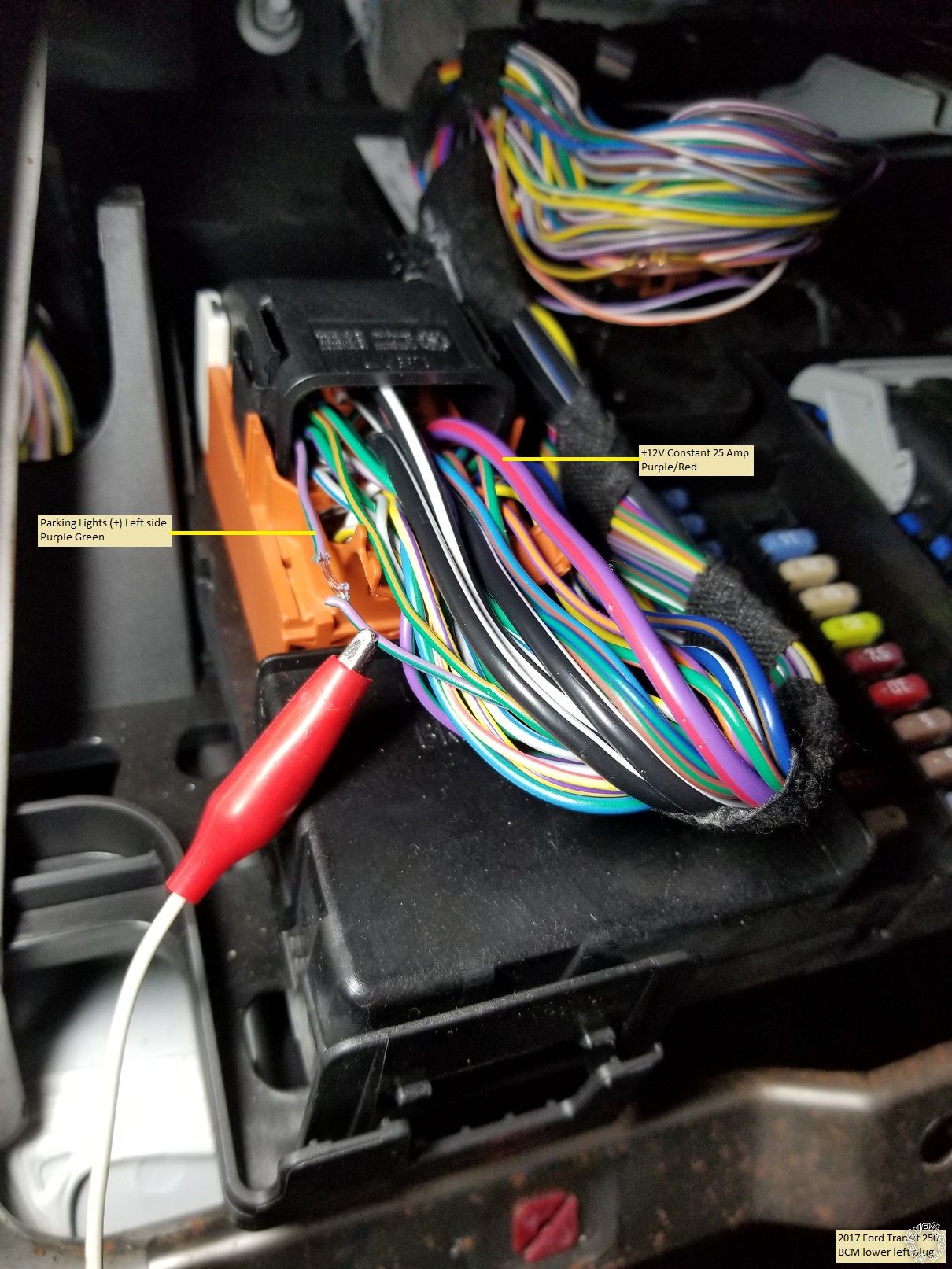
The lower left connector has the left side Parking Light wire as shown.
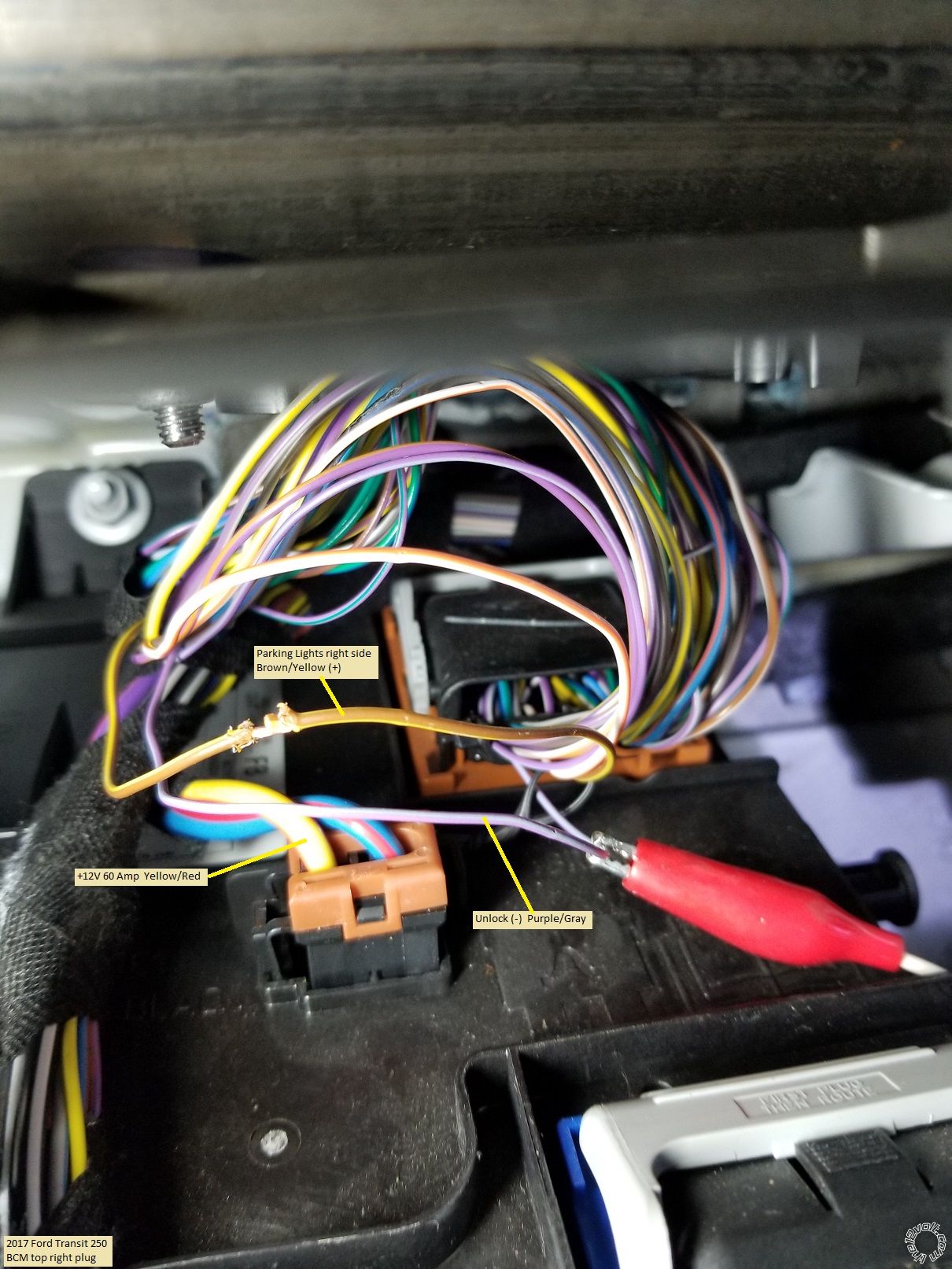
The connector at the upper right has two needed wires.
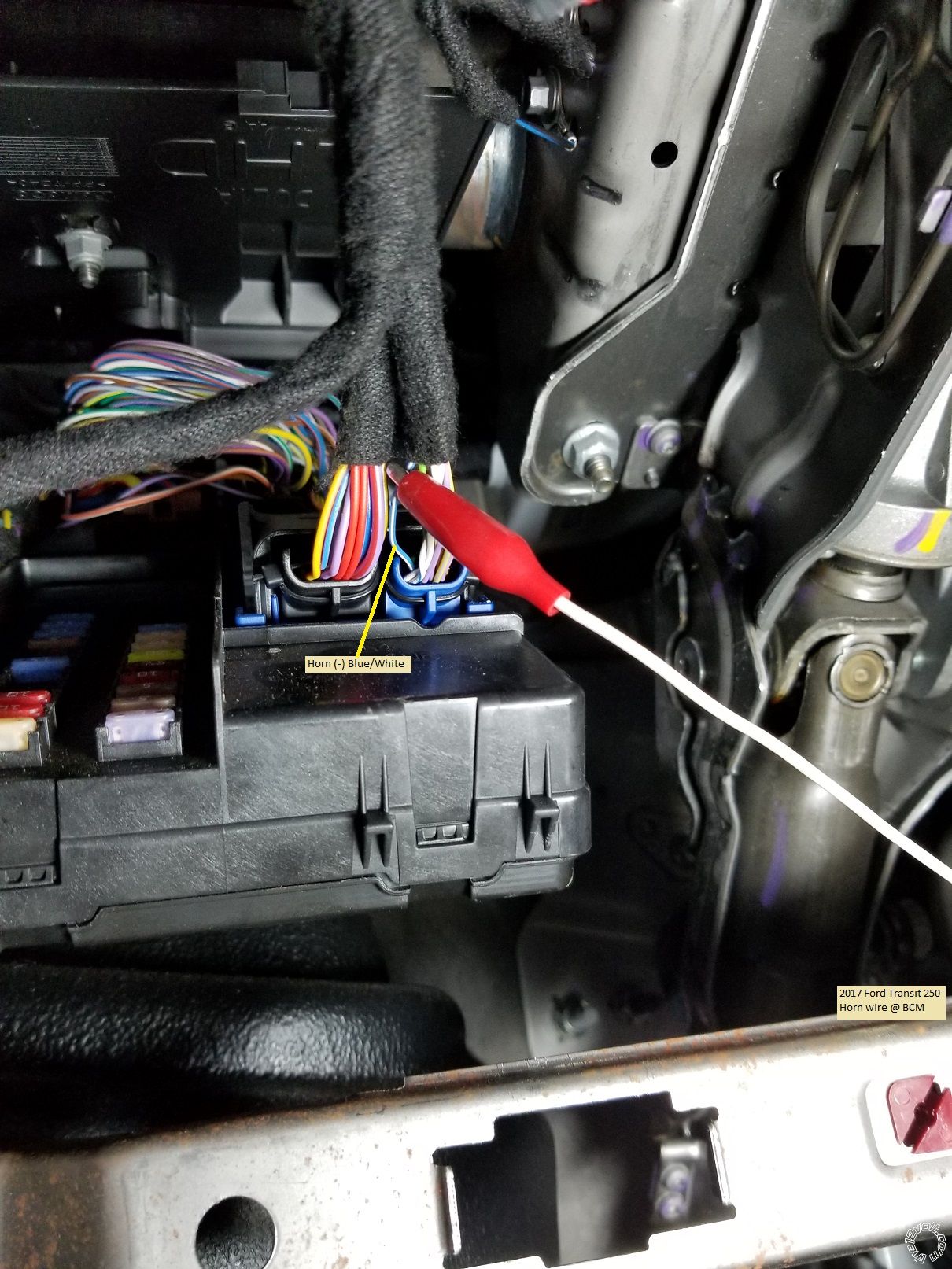
The bottom right plug has the Horn wire ( optional ).
As shown, +12 Volt constant power can be obtained from either wire indicated in the above pictures. With a basic Avital 4115 system and it's low power draw, using the Purple/Red wire is acceptable.
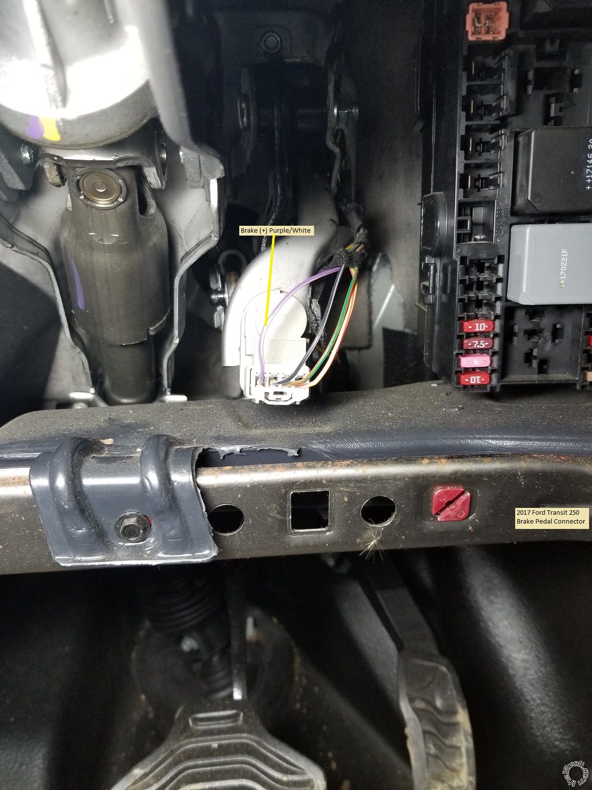
The Brake wire is easiest to obtain at the Brake Pedal switch as shown below :
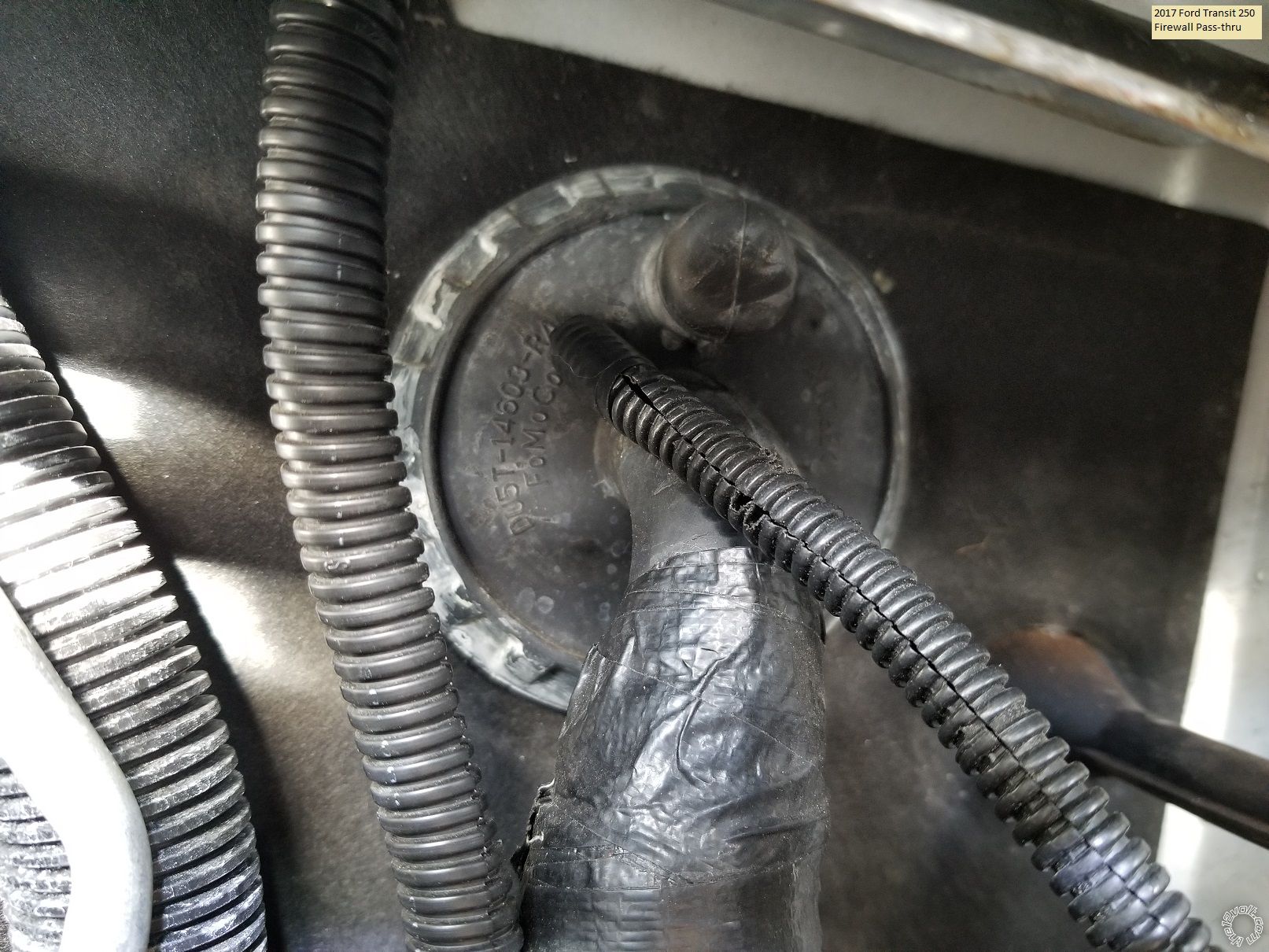
For the Hood Pin wire, there is a large rubber grommet behind the BCM and strut tower for firewall pass-thru as shown in the following photos.
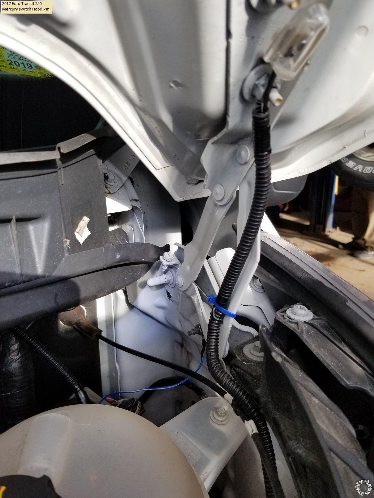
Besides the 4115 R/S system, you will need two 3 Amp diodes. If you choose not to use the 4115 kit supplied hood pin, a Direct 8613 tilt switch is a good, rust-free choice. Total cost ~ $60.
Below is the necessary wiring if you use an Avital or Viper 4115 R/S system.
H1/1 LIGHT GREEN/BLACK....... FACTORY ALARM DISARM............. not used
H1/2 GREEN/WHITE.................... FACTORY REARM.............................. not used
H1/3 YELLOW............................... (+) IGNITION OUT (TO ALARM)....... not used
H1/4 WHITE/BLUE....................... (-) ACTIVATION INPUT........................not used
H1/5 ORANGE............................... (-) GROUND WHEN LOCKED............ not used
H1/6 BROWN................................ (-) HORN OUTPUT................................. Blue/White @ BCM
H1/7 RED/WHITE......................... (-) TRUNK RELEASE OUTPUT........... not used
H1/8 BLACK.................................. GROUND................................................. Chassis Ground
H1/9 WHITE.................................. (+/-) LIGHT FLASH... set to (+)............. Diode split* to Purple/Green and
...............................................................................................................................Brown/Yellow @ BCM
* The two 3 Amp diodes are necessary to keep the right and left side Parking Lights seperated.
Install the diodes with the bands towards the vehicle wires.
H3/1 BLACK/WHITE............ (-) NEUTRAL SAFETY SWITCH INPUT...... to H1/8 Chassis Ground
H3/2 VIOLET/WHITE.......... TACHOMETER INPUT WIRE........................ not used
H3/3 BROWN......................... (+) BRAKE SWITCH SHUTDOWN WIRE.... Purple/White @ Brake Pedal switch
H3/4 GRAY............................. (-) HOOD PINSWITCH..................................... to Hood Pin switch
H3/5 BLUE/WHITE.............. (-) 200mA 2ND STATUS/REAR DEFOG........... not used
4-pin satellite harness diagram
1 BLUE........... (-) STATUS OUTPUT.............. not used
2 ORANGE.... (-) ACCESSORY OUTPUT..... not used
3 PURPLE..... (-) STARTER OUTPUT........... not used
4 PINK........... (-) IGNITION OUTPUT........... not used
Heavy gauge relay wiring diagram
1 RED...................... (+) (30A) HIGH CURRENT 12 INPUT........... Purple/Red @ BCM fused at 25 Amps
2 PINK/WHITE...... (+) PROGRAMMABLE OUTPUT.................. not used
3 RED...................... (+) (30A) HIGH CURRENT 12V INPUT........ combined with Pin 1 Red
4 ORANGE............. (+) (30 AMP) OUTPUT TO ACC..................... Purple/Green @ Ignition Switch
5 PURPLE.............. (+) (30 AMP) OUTPUT TO STARTER............ Blue/White @ Ignition Switch
6 PINK.................... (+) (30 AMP) OUTPUT TO IGNITION........... Brown/Yellow @ Ignition Switch
Door lock harness, 3-pin connector
1 LIGHT BLUE..... (-) UNLOCK OUTPUT...... Purple/Gray @ BCM
2 EMPTY............... NOT USED
3 GREEN............... (-) LOCK OUTPUT............. not used
There are many good locations to make the Chassis Ground connection
under the dash.
Avital 4115 programming :
Menu 1 Feature 1 to Option 2 ( if you made the horn connection )
Menu 2 Feature 1 to Option 3 ( van has "one-touch" starting )
Menu 2 Feature 4 to Option 3 ( one second Starter output )
Menu 2 Feature 5 to Option 2 ( two button presses to prevent false start-ups )
That should do it. Solder all your connections. Ensure that the tilt / telescopic steering wheel adjustments won't chaff R/S ignition wires. Test everything and put it all back together.
Soldering is fun!
Posted by: shirtswhite.blogspot.com
Source: https://www.the12volt.com/installbay/forum_posts.asp?tid=145130